





An X-ray inspection system operates as a single acquisition chain
A typical digital X-ray inspection system can be understood as the following flow: X-ray Source → Object → Detector → Readout → Digital Data → Acquisition Software → Image Processing / Inspection.
These components do not operate independently. Even if a detector supports a high line rate, inconsistent conveyor motion or acquisition timing can make the sampling interval in the direction of travel uneven.
Conversely, even fast software processing cannot sustain continuous acquisition if the detector interface or data transfer path does not provide sufficient throughput.
Therefore, system design should go beyond checking detector specifications and verify that Geometry → Motion → Timing → Data → Software work together as one acquisition chain. In X-ray imaging systems based on a linear detector array, acquisition may also be started by an external signal, and detector lines may be repeatedly read out to build a data matrix.
Geometry — the positions of the source, object, and detector affect the image
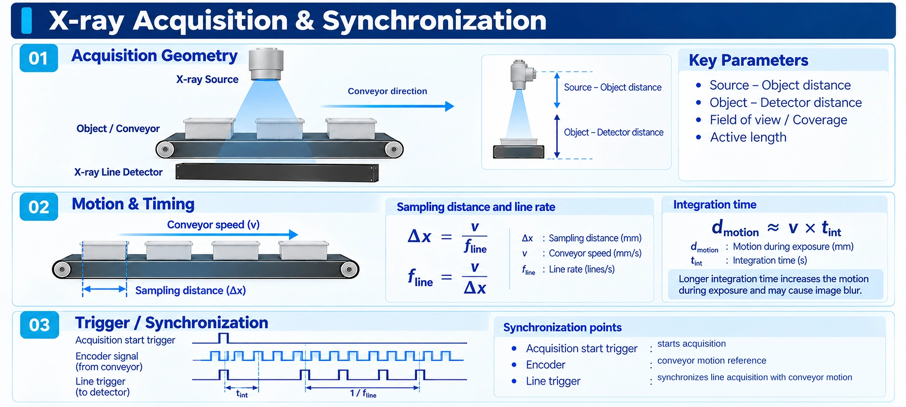
The resulting X-ray image is affected by the relative positions of the source, object, and detector. Major geometry factors include Source-to-Detector Distance, Object-to-Detector Distance, X-ray Beam Coverage, Detector Active Area or Active Length, X-ray Source Focal Spot, and Object Position.
If the detector is not adequately covered by the X-ray beam across the required area, signal may be insufficient in part of the image or the required inspection width may not be fully covered.
The distance between the object and detector, together with the source geometry, can also affect magnification and geometric unsharpness. Final spatial resolution is therefore not determined by detector pixel pitch alone.
For system design, it is important to review Inspection Width → Source Beam Coverage → Detector Active Length → Source / Object / Detector Geometry together. Even if the detector has sufficient active length, the full inspection width cannot be used effectively if the beam coverage and installation geometry do not match.
Trigger and Synchronization — when should data be acquired?
A digital detector may acquire data according to its internal timing or may synchronize acquisition timing with a signal from an external device.
With an internal trigger, acquisition follows timing generated by the detector or acquisition system. With an external trigger, the start or timing of acquisition is synchronized to a trigger signal supplied by an external device.
An external trigger can be used when image acquisition timing must be coordinated with an X-ray source, conveyor, motion controller, or another system controller. In a line-detector system, however, it is important to distinguish the trigger that starts acquisition from the timing used to acquire each line.
Depending on the system configuration, an encoder or motion signal can be used to relate each line acquisition to actual travel distance. The relationship Object Motion ↔ Trigger / Encoder ↔ Line Acquisition is therefore important in line-detector systems.
If timing is inconsistent, the sampling interval in the travel direction changes and the resulting image may appear stretched or compressed.
Conveyor speed and line acquisition must be matched
As discussed in Technical Insight 09, conveyor speed and line rate determine the sampling interval in the direction of travel.
- Δx
- Sampling distance in the direction of travel
- v
- Conveyor speed
- fline
- Line rate
Use a consistent time base for conveyor speed and line rate.
Conversely, if the required sampling distance in the travel direction is known, the line rate required for the target conveyor speed can be calculated. Conveyor speed and line rate should use a consistent time base.
- fline
- Required line rate
- v
- Conveyor speed
- Δx
- Target sampling distance in the direction of travel
If the target sampling distance is known, the required line rate can be calculated from the conveyor speed.
It is important to distinguish sampling along the detector array from sampling in the conveyor direction. Sampling along the detector array is mainly related to pixel pitch, while sampling in the conveyor direction is determined by the relationship between conveyor speed and line rate.
If object speed changes, acquisition timing must also follow that change to maintain consistent spatial sampling. In addition to acquiring lines at fixed time intervals, practical systems may use encoder pulses or motion signals to relate acquisition to travel distance.
The key point is not simply how many lines are acquired per unit time, but how consistently each line acquisition corresponds to the actual distance traveled by the object. This synchronization becomes especially important on production lines where conveyor speed varies.
Data Interface — acquired data must be transferred fast enough
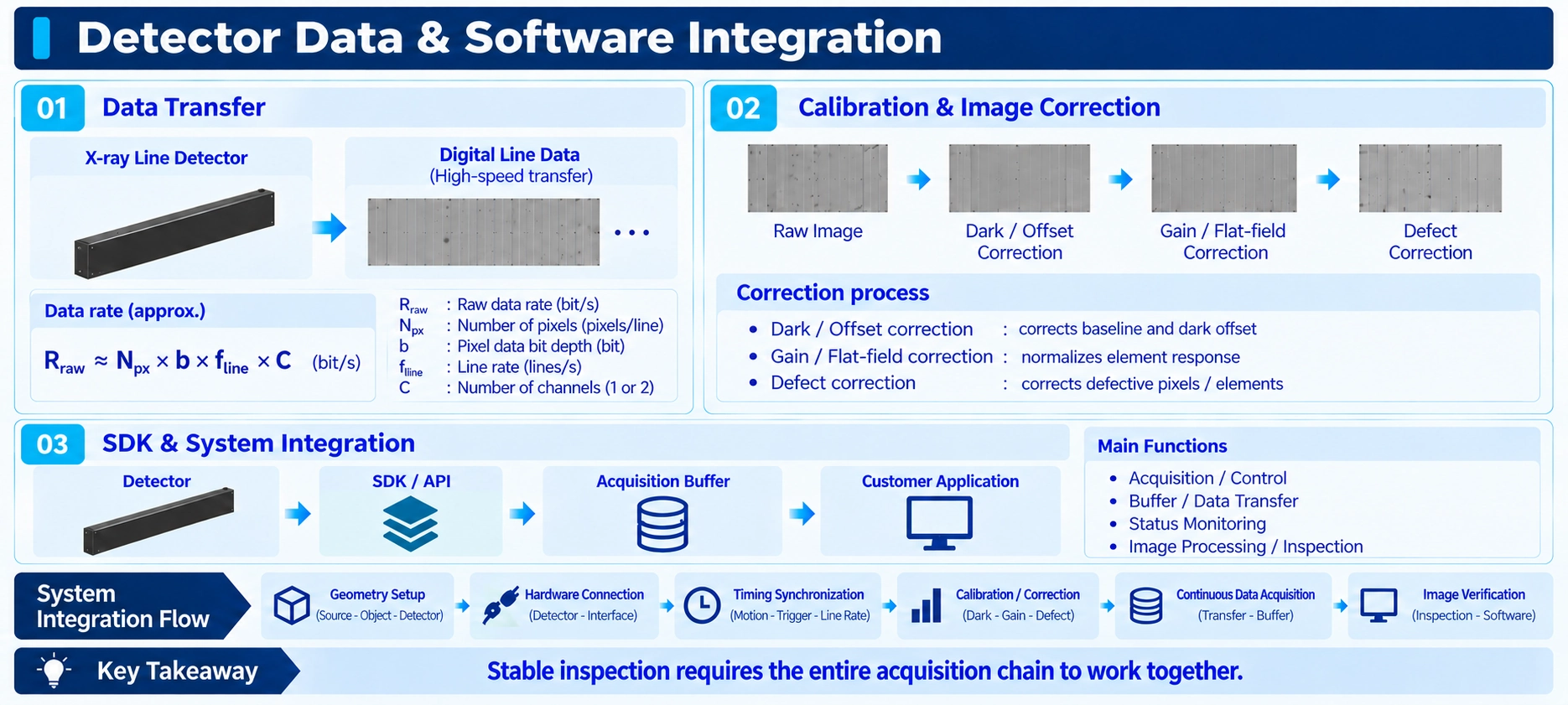
Data generated by the detector must be transferred continuously to the acquisition PC or controller. The required raw data rate is related to the number of pixels per line, data bits per pixel, line rate, and the number of data channels acquired at the same time.
- Rraw
- Raw data rate
- Npx
- Number of pixels per line
- b
- Data bits per pixel
- fline
- Line rate
- C
- Number of data channels acquired simultaneously
This is a conceptual raw data rate and does not include protocol overhead, headers, packing, or buffering.
For example, with 16-bit data, the raw data size per pixel can generally be considered as 16 bits = 2 bytes. A dual-energy system that acquires LE and HE data simultaneously may therefore require higher raw-data throughput than a single-energy system.
Actual data transfer also includes headers, packet structure, protocol overhead, buffering, and data packing, so the equation below is a conceptual estimate. If the pixel count and bit depth remain the same, doubling the line rate approximately doubles the required raw-data throughput.
When evaluating a detector interface, it is therefore not enough to check whether the interface is supported. The system must be able to sustain the required data transfer at the target resolution and acquisition rate. Industrial imaging systems may use interfaces such as USB, GigE Vision, and Camera Link, while the actual interface and transfer architecture depend on the detector and system configuration.
Calibration and image correction are part of system integration
Individual detector pixels or elements may not have perfectly identical responses. Actual images can also be affected by dark offset, pixel sensitivity differences, X-ray field non-uniformity, detector or scintillator artifacts, and defective pixels or elements.
Digital X-ray systems may therefore use calibration or image-correction processes such as dark / offset correction, gain / flat-field correction, and defect correction.
A key point is that the final correction result can be affected when the calibration reference differs substantially from the actual imaging conditions. Calibration is therefore better understood as a system-level process that considers the detector, X-ray source, and operating conditions together rather than as a one-time detector setting.
When conditions such as tube voltage, tube current, filtration, exposure conditions, acquisition rate, or gain change, the calibration conditions should also be reviewed.
SDK and software connect the detector to the actual system
Even if the detector hardware generates data correctly, it cannot be used in an inspection machine unless the system software can control the detector and receive its data.
Detector integration software may require functions such as detector initialization, acquisition start / stop, exposure or integration-time settings, trigger-mode settings, line / frame data acquisition, application of calibration data, error / status monitoring, data-buffer management, and integration with image-processing software.
These functions are often implemented through an SDK, API, or driver supplied by the detector manufacturer. Detector selection should therefore consider not only hardware specifications but also SDK availability, supported programming environments, control of acquisition parameters and trigger / timing settings, raw-data access, and the ability to monitor buffer and error status during continuous acquisition.
In this sense, an SDK is not merely software for displaying detector data. It is an integration layer that connects detector hardware to the actual inspection application.
Stable integration requires validation of the entire system
Successful operation in a standalone detector test does not guarantee the same performance on an actual production line. The final system should be evaluated by considering geometry, timing, signal, data, correction, and software together.
Geometry checks include source and detector position, beam coverage, and inspection width. Timing checks include trigger, line rate, conveyor speed, and integration time. Signal checks include X-ray exposure, detector signal, noise, and saturation. Data checks include interface bandwidth, buffering, and continuous acquisition.
Correction checks include Dark / Gain / Defect Correction, while software checks include the SDK, API, driver, and integration with image-processing software. In a real production environment, it is especially important to verify not only a single successful image capture but also stable continuous data acquisition over an extended period at the target conveyor speed.
A practical validation sequence is Geometry Setup → Hardware Connection → Timing Synchronization → Calibration / Correction → Continuous Data Acquisition → Image Verification. After confirming each stage, the overall system performance can be evaluated.
- The detector is one component of an X-ray inspection system and must operate together with the source, motion system, and software.
- Source–Object–Detector geometry affects inspection coverage and spatial resolution.
- Sampling along the detector array and sampling in the conveyor direction are determined by different factors.
- Synchronization between conveyor motion and line acquisition is important in line-detector systems.
- An external trigger can synchronize acquisition timing with external equipment, and an encoder or motion signal can relate each line acquisition to travel distance depending on the system configuration.
- An interface should be evaluated not only for connectivity but also for its ability to sustain the required data throughput.
- Dual-energy systems may require higher data throughput because multiple data channels are acquired.
- Calibration and image correction should consider the actual X-ray source and operating conditions, not the detector alone.
- SDKs and APIs are important integration layers that connect detector hardware to inspection software.
- Final inspection performance is the result of the entire system integration, not a single detector specification.
- IAEA — An Introduction to Practical Industrial Tomography Techniques for Non-destructive Testing (NDT), IAEA-TECDOC-1931. Example reference for the use of external signals, detector acquisition, and repeated line readout to construct a data matrix in linear detector array imaging systems.
- Hamamatsu Photonics — X-ray Flat Panel Sensor Instruction Manual for GigE Interface Type. Reference for internal / external trigger and acquisition synchronization concepts.
- Hamamatsu Photonics — X-ray Flat Panel Sensor Application Manual. Reference for Dark / Shading / Defect Correction and calibration / reference conditions.
- Allied Vision — Set a line trigger. Reference for LineStart triggering with an encoder or external signal and acquisition synchronization in the direction of motion.
- Teledyne DALSA — Sapera LT Vision Software / SDK. Reference for image acquisition, camera control, data transfer, and SDK integration architecture.


