





Pixel Pitch — how finely the detector samples space
Pixel pitch is the distance between the centers of adjacent detector elements. For example, a line detector with a 0.4 mm pixel pitch can be understood as sampling the X-ray signal at approximately 0.4 mm intervals along the detector-array direction.
A smaller pixel pitch generally enables finer spatial sampling, but it does not necessarily mean higher spatial resolution.
Actual spatial resolution is influenced by the true sensitive area of the detector element, signal spread in the scintillator or conversion layer, the X-ray source focal spot, object–detector geometry, motion blur, signal processing, and other factors.
Pixel pitch is therefore an important specification for sampling interval, but it is not the same as actual spatial resolution.
Active Length and Number of Elements — how wide an area can be inspected
In a line detector, the number of elements and pixel pitch are important for understanding inspection width. In a simplified form, Active Length ≈ Number of Elements × Pixel Pitch.
This relationship is best treated as a nominal value when detector elements are regularly spaced and the effective element width is similar to the pixel pitch. In a real product, the manufacturer-defined active length can differ from the simple calculation because of sensitive width, inter-element gaps, edge margins, module boundaries, and inactive regions.
For actual system design, the manufacturer-specified active length should therefore be used as the final reference rather than the simple calculated value. A longer active length is not always better; a detector much longer than the required inspection width may add unnecessary system size, cost, and data throughput.
Line Rate, Integration Time, and Conveyor Speed are connected
Line rate indicates how many lines of data a line detector can acquire over a given period. Assuming one line is acquired per acquisition at a constant conveyor speed, if the line rate is f_line and conveyor speed is v, the distance traveled by the object per line acquisition can be expressed as Δx = v / f_line.
The line period can also be expressed as T_line = 1 / f_line. In general, integration time must fit within one line period, giving t_integration ≤ T_line. The actual maximum integration time can be shorter than the line period depending on detector readout, reset, and internal timing architecture.
If conveyor speed increases while line rate stays the same, the sampling interval in the direction of travel becomes larger. Conversely, maintaining the same sampling interval at a higher conveyor speed requires a higher line rate.
As line rate increases, however, the total time available for each line acquisition becomes shorter and integration time may also be limited. A shorter integration time can reduce the X-ray signal collected per line, so noise and SNR must be considered together.
A higher line rate is therefore not always better. The goal is to find a combination of line rate and integration time that provides sufficient signal while meeting the required conveyor speed and spatial sampling.
Bit Depth, ENOB, and Dynamic Range do not mean the same thing
Bit depth indicates how many digital codes an A/D converter can use to represent a signal. An ideal 16-bit ADC, for example, can represent 2^16 = 65,536 digital codes.
This does not mean that all 65,536 levels can be distinguished as useful signal in practice. Real ADCs are affected by noise, distortion, non-linearity, the analog front end, and other limitations.
ENOB (Effective Number of Bits) indicates the effective resolution of an ADC after practical noise and distortion are considered. When SINAD is used, a common relationship is ENOB = (SINAD − 1.76) / 6.02.
ENOB is fundamentally an ADC performance metric and is not the same as the dynamic range of the complete detector system. Dynamic range generally describes the usable range between a high signal level that can be measured without saturation and a low signal level that can still be distinguished above limitations such as noise. The exact definition and measurement conditions can vary by manufacturer or system.
It is therefore incorrect to treat 16-bit = 16-bit ENOB = Dynamic Range 65,536:1 as equivalent statements. Bit depth describes digital encoding capability, ENOB describes effective ADC performance, and system dynamic range is a separate concept related to noise and saturation across the detector and readout chain.
Sensitivity and SNR are different concepts
Sensitivity generally describes how much the detector output signal changes in response to a change in incident X-rays under specified X-ray-energy and exposure conditions. The exact definition and units can vary by manufacturer and measurement method, so test conditions should be checked when comparing different detectors.
Higher sensitivity can help produce a larger signal under the same conditions, but it does not always mean better image quality.
Even a large detector signal can make small signal differences difficult to distinguish if noise is also large. Practical image evaluation should therefore consider not only absolute signal level but also the relationship between signal and noise, including SNR and CNR.
This is directly related to the concepts discussed earlier in 06. Contrast & Noise.
Energy Response — detector response can vary with X-ray energy
The response of an X-ray detector may not be identical at every photon energy. X-ray absorption efficiency and output-signal characteristics can vary with detector material, scintillator type and thickness, conversion-layer structure, and other factors.
An X-ray tube also produces a spectrum of photon energies rather than a single energy, with the spectrum determined by tube voltage, target material, filtration, and related conditions.
A detector that shows high sensitivity under one condition should therefore not be assumed to have the same relative performance under a different X-ray energy condition. Detector selection should consider the actual X-ray energy range together with the attenuation characteristics of the object being inspected.
Specifications should be evaluated together with system conditions
A common mistake when comparing detector specifications is to treat each number as an independent ranking. Assuming that a smaller pixel pitch, a higher line rate, more bits, or higher sensitivity is always better can lead to the wrong choice under real inspection conditions.
In a practical system, relationships such as Pixel Pitch ↔ Spatial Sampling, Line Rate ↔ Conveyor Speed ↔ Integration Time, Signal ↔ Noise ↔ SNR, Bit Depth ↔ ENOB ↔ Dynamic Range, and Energy Response ↔ X-ray Spectrum ↔ Object Attenuation exist at the same time.
The goal of detector evaluation is therefore not to find the highest individual specification, but to select a combination of specifications that can reliably provide the required image information for the inspection object and system conditions.
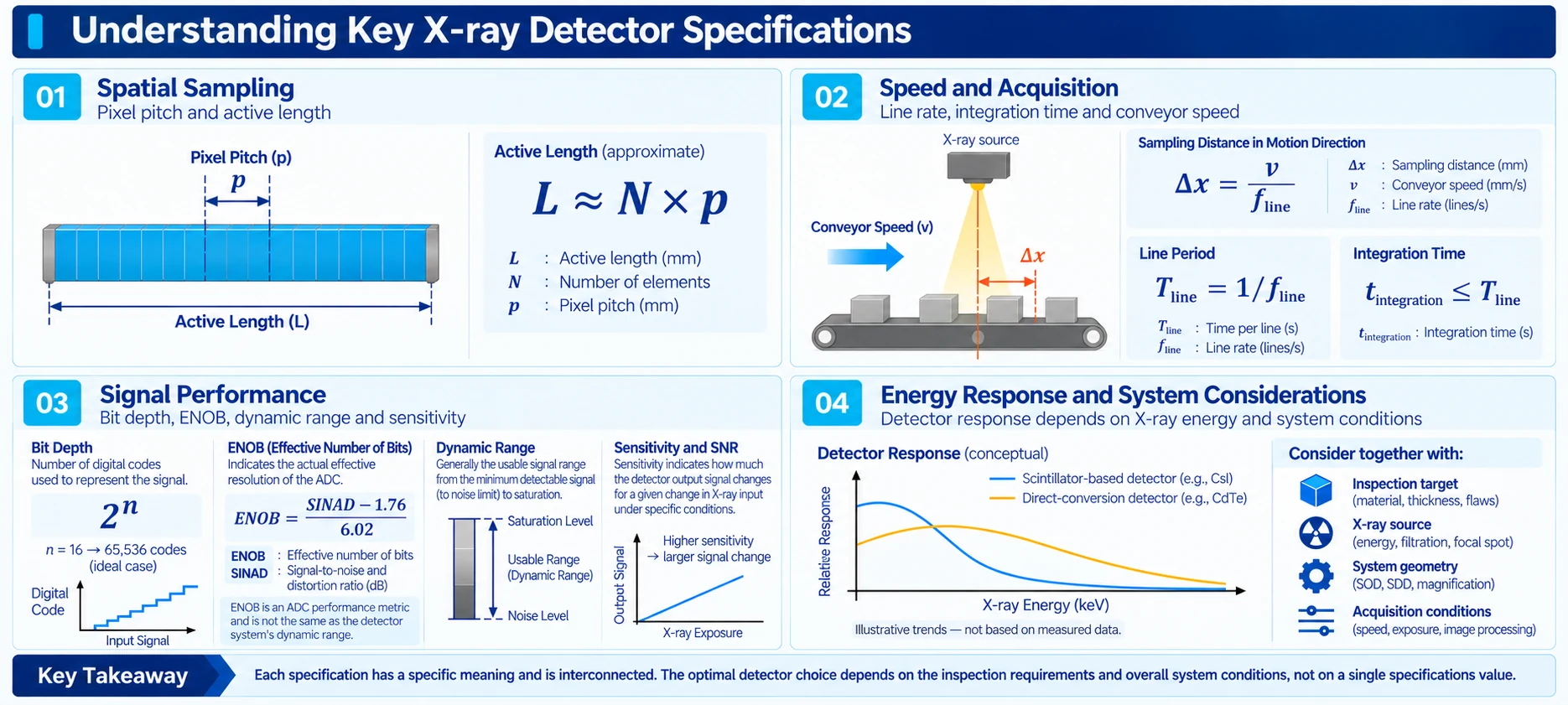
- Pixel pitch describes spatial sampling interval and is not the same as actual spatial resolution.
- Active length is related to inspection width, but the manufacturer-defined specification should be checked rather than relying only on a nominal calculation.
- Line rate should be interpreted together with conveyor speed, line period, and integration time.
- Bit depth, ENOB, and dynamic range are different concepts, and ENOB is fundamentally an ADC performance metric.
- Sensitivity can be defined differently depending on measurement conditions, and high sensitivity alone does not determine image quality.
- Detector response can vary with X-ray energy and with detector material and conversion-layer characteristics.
- Detector specifications should be evaluated as a combination matched to the inspection object and system conditions rather than as isolated higher-or-lower numbers.
- IAEA — Design, Development and Optimization of a Low Cost System for Digital Industrial Radiology, Radiation Technology Reports No. 2. Reference for detector pitch, spatial resolution, SNR / CNR, and dynamic-range concepts.
- IAEA — Diagnostic Radiology Physics: A Handbook for Teachers and Students, Chapters 4 & 7. Reference for sampling pitch, detector aperture, spatial resolution, image quality, and digital detector architecture.
- NIST — An Overview of Advances in Signal Processing Techniques for Classical and Quantum Wideband Synthetic Apertures. Reference for ADC quantization and the relationship between SINAD and ENOB.


