


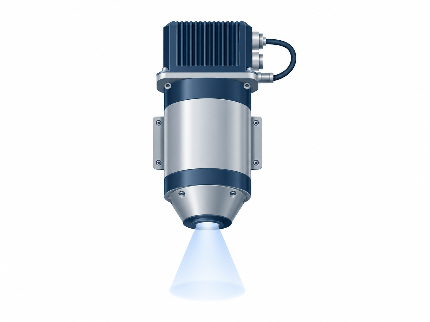
X-ray Emission
X-rays are emitted from the X-ray source toward the object under inspection.

X-RAY LINE DETECTOR
AiST is a professional x-ray detector manufacturer
This page summarizes key technical information on industrial X-ray inspection systems,
from the basic principles of X-ray Line Detectors to product selection and inspection conditions.
Rather than simply listing product specifications, this guide explains how X-ray Line Detectors work and which criteria should be considered when selecting a detector and defining inspection conditions.
Learn where the detector is installed in an inspection system, what transmitted X-ray signal it receives, and how that signal becomes image data.
View DetailsUnderstand the difference between using a single image dataset and using low-energy and high-energy data together.
View DetailsLearn how to select pixel pitch and active area based on the required level of detail and actual inspection width.
View DetailsSee how material and thickness, X-ray conditions, inspection speed, calibration, and image-processing settings affect inspection results.
View DetailsCompare FLIES C, MiUS D, and DANO T based on imaging requirements, pixel pitch, and application.
View DetailsAn X-ray Line Detector uses a linear sensor to continuously acquire one line of data from X-rays transmitted through the object under inspection. As the object moves, successive line data are combined in sequence to build a two-dimensional X-ray image.
X-rays are emitted from the X-ray source toward the object under inspection.
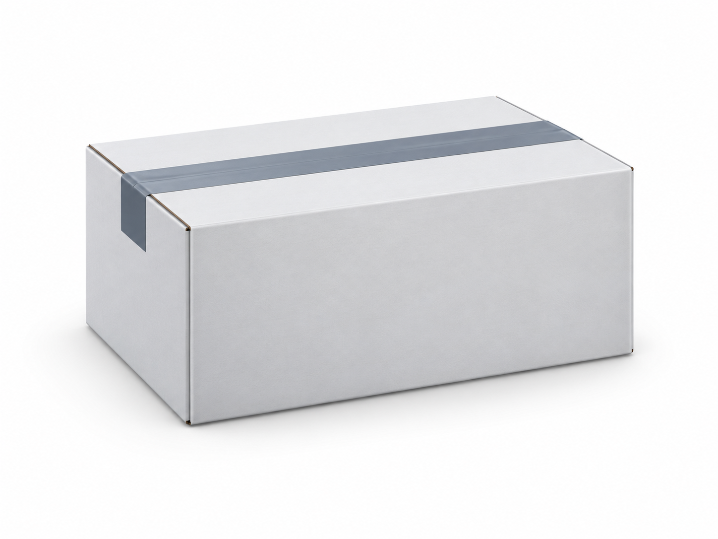
As X-rays pass through the object under inspection, they are attenuated differently depending on material composition, density, and thickness.
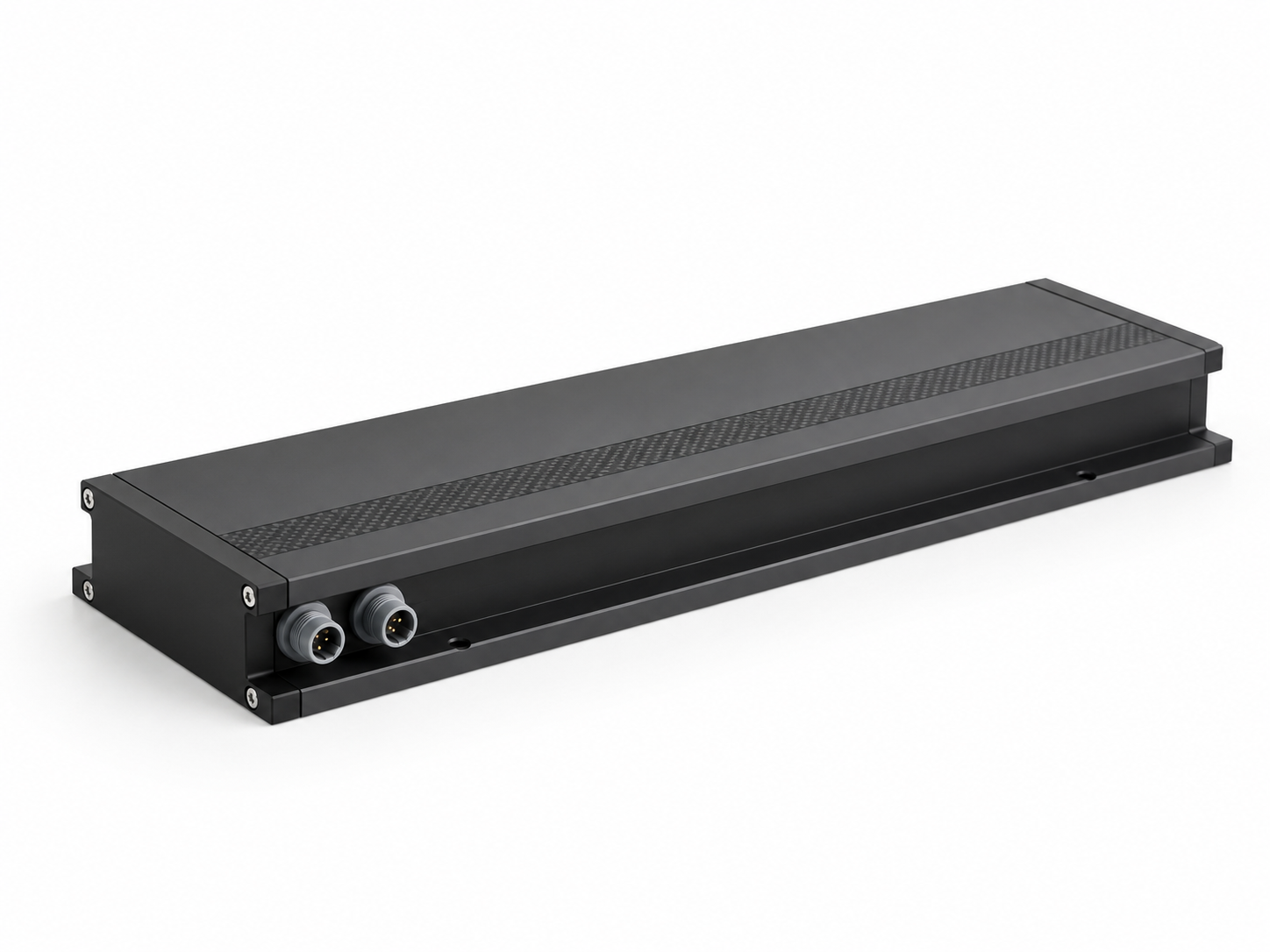
Transmitted X-rays reach the Line Detector installed beneath the conveyor and are detected.
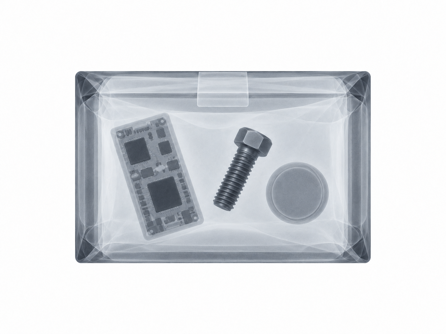
Successive line data are combined to form the final X-ray image.
The Line Detector is installed below the conveyor, facing the X-ray source, and acquires changes in transmitted X-ray intensity as line data.
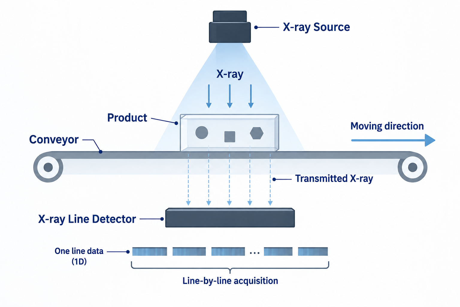
The X-ray source is positioned above the object under inspection, while the Line Detector is installed below the conveyor. X-rays transmitted through the object reach the detector, which continuously acquires data from the same scan position as the object moves.
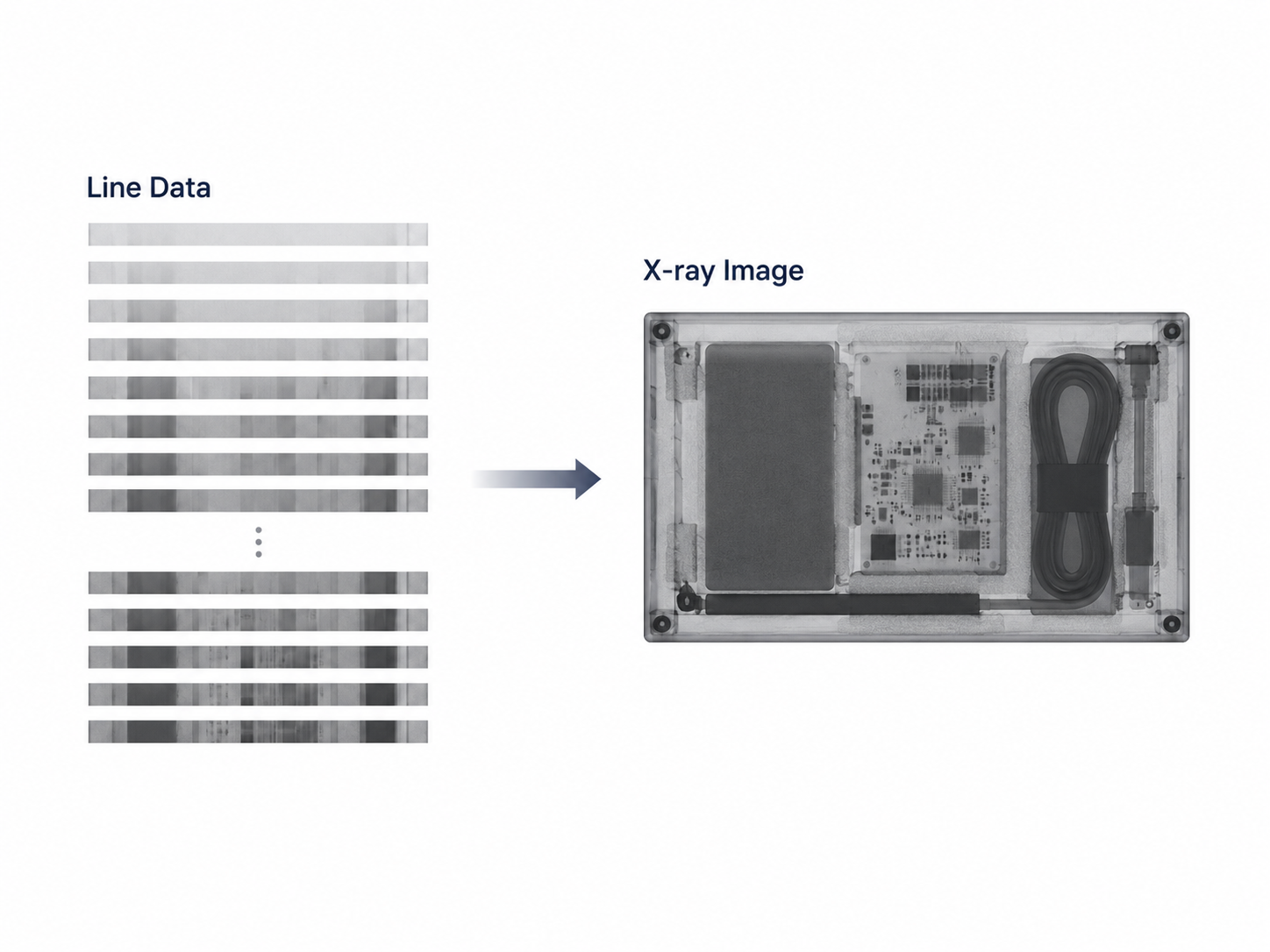
Each acquisition generates one line of data. As the object under inspection moves, successive lines are acquired and stacked in sequence to form a two-dimensional X-ray image.
The detector remains fixed at the inspection position while the object under inspection moves along the conveyor.
Line data are repeatedly read from the same detection position in synchronization with the movement of the object under inspection.
Multiple lines acquired over time are combined to form the complete inspection image.
Both methods detect X-rays transmitted through the object under inspection, but the type of information acquired is different. Single Energy uses one set of image data, while Dual Energy uses low-energy and high-energy data together to analyze material differences.
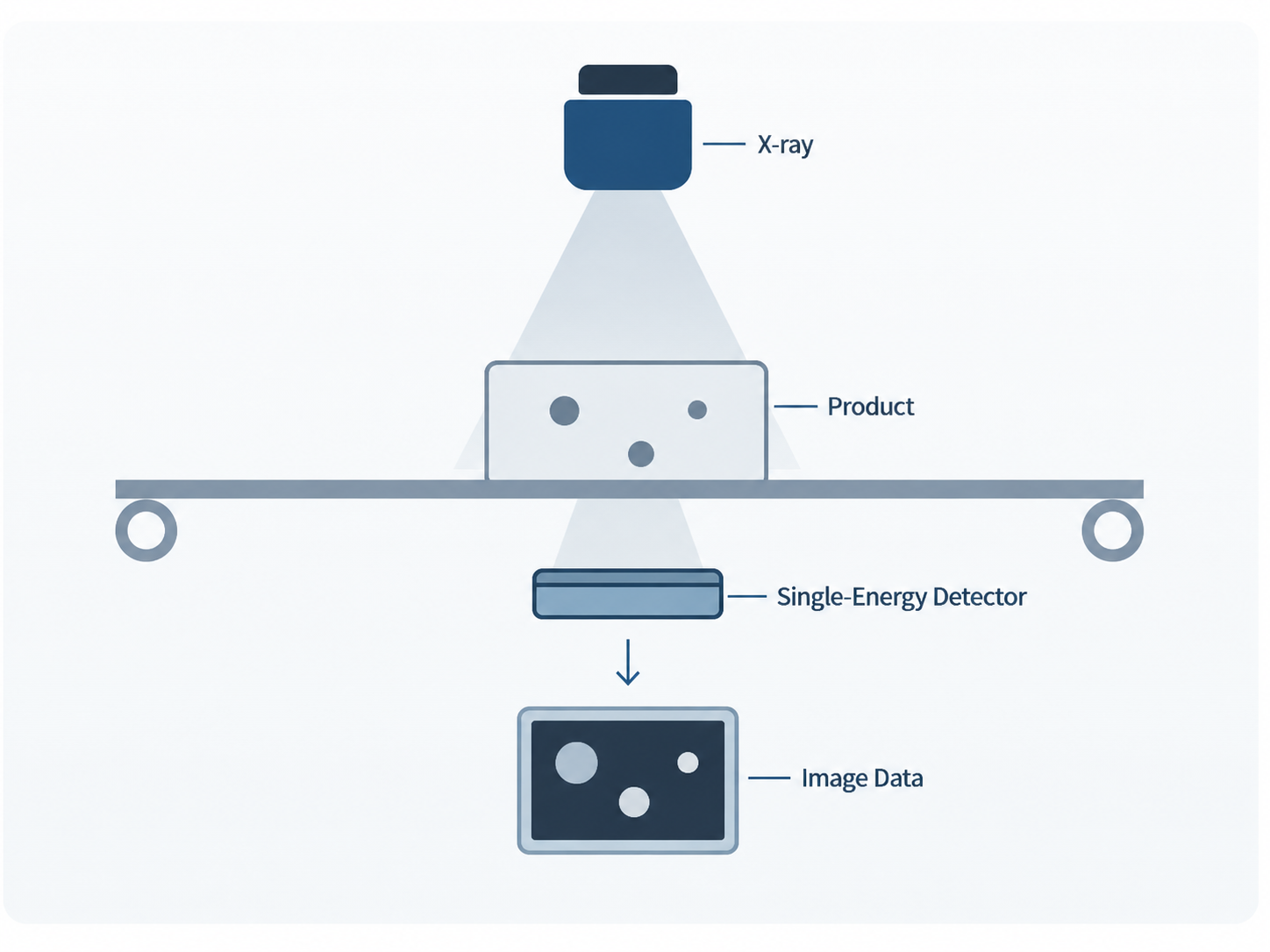
Attenuation information from transmitted X-rays is acquired as a single image dataset. This approach is widely used for general transmission imaging, foreign-object detection, and industrial X-ray inspection.
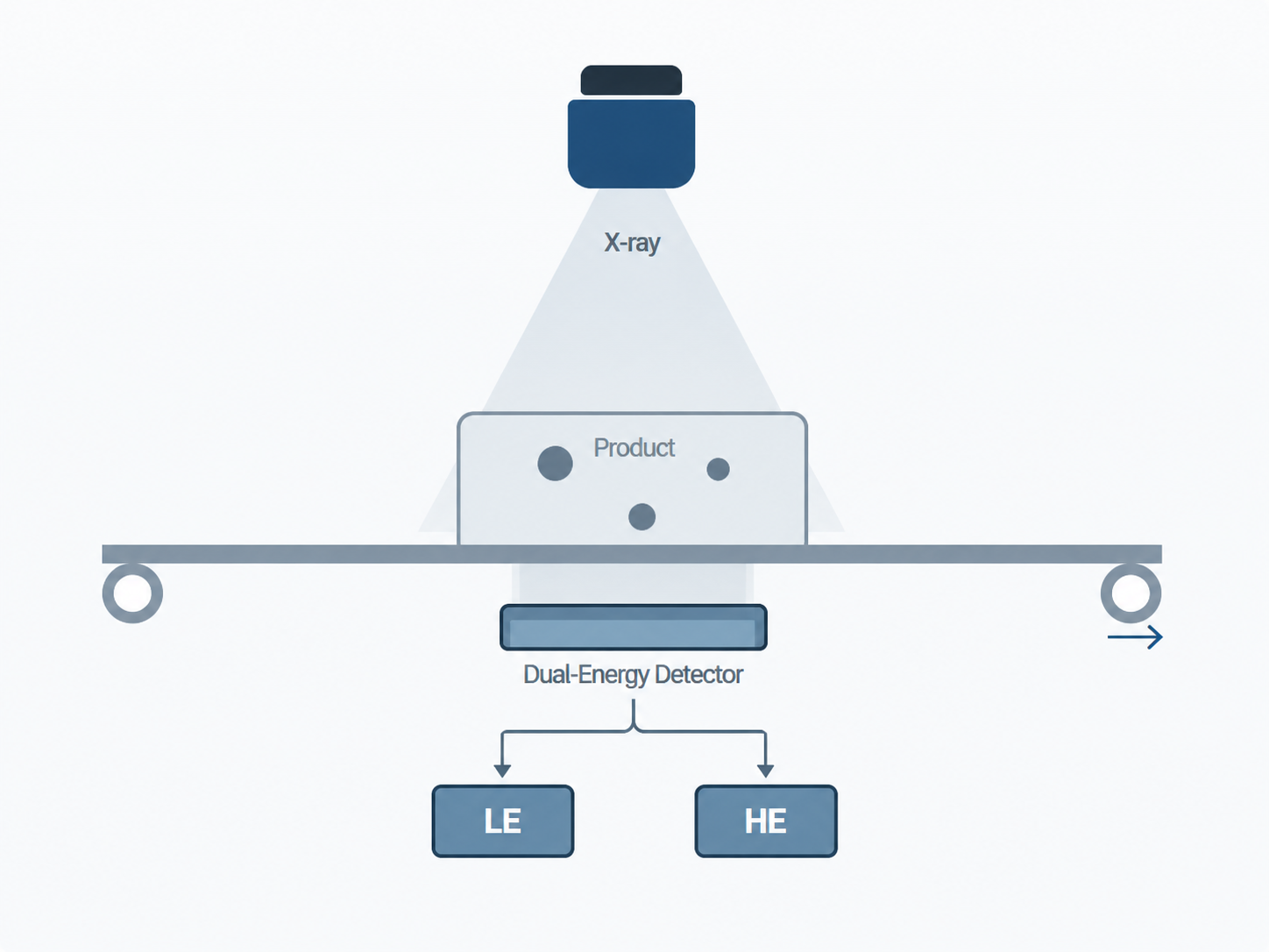
Low-energy (LE) and high-energy (HE) data are acquired from the same object under inspection. Their energy-dependent attenuation characteristics provide additional information for differentiating materials that may appear similar in a single-energy image.
MiUS D acquires low-energy (LE) and high-energy (HE) data within a single X-ray inspection system and uses their different attenuation responses to support material differentiation.
When selecting a line detector, consider both the level of detail that must be resolved and the width that must be inspected across the production line.
Pixel pitch is the spacing between adjacent detector elements. In general, a smaller pitch is advantageous for resolving finer structures, but actual detection performance is determined together with X-ray conditions, object thickness, and inspection speed.
Active area is the sensor region that can detect X-rays. The required length should be selected according to the inspection width and installation geometry, and available lengths vary by product series.
Final detection performance is not determined by detector pixel pitch or sensitivity alone. The inspection object, X-ray and acquisition conditions, line speed, calibration, and image processing must be considered as a complete system.
X-ray attenuation varies with material composition, density, and thickness. These factors also affect the contrast between the object under inspection and the material or feature being detected.
Tube voltage and tube current affect X-ray penetration and photon flux, while integration time affects the amount of signal acquired by the detector. These conditions should be optimized for the object under inspection.
If conveyor speed and line acquisition rate are not properly matched, image geometry and signal quality can be affected.
Offset and gain calibration, together with appropriate post-processing settings, helps reduce sensor variation and improve image stability.
Even with the same detector, results can vary depending on the object under inspection and X-ray conditions. Before final product selection, image quality should be evaluated using actual samples at the target inspection speed.
Imaging requirements and resolution vary depending on the inspection purpose. Use the criteria below to compare AiST TECH product lines.
A Single Energy line detector suited to general industrial X-ray transmission imaging and foreign-object inspection.
A Dual Energy line detector that combines low-energy and high-energy data to differentiate materials that may be difficult to distinguish in a single-energy image.
A TDI line detector with a 0.2 mm pixel pitch for inspection applications that require finer X-ray image detail.
Tell us what you need to inspect, the target feature or foreign object size, inspection width, and line speed. We can review the applicable detector and recommended test approach.


